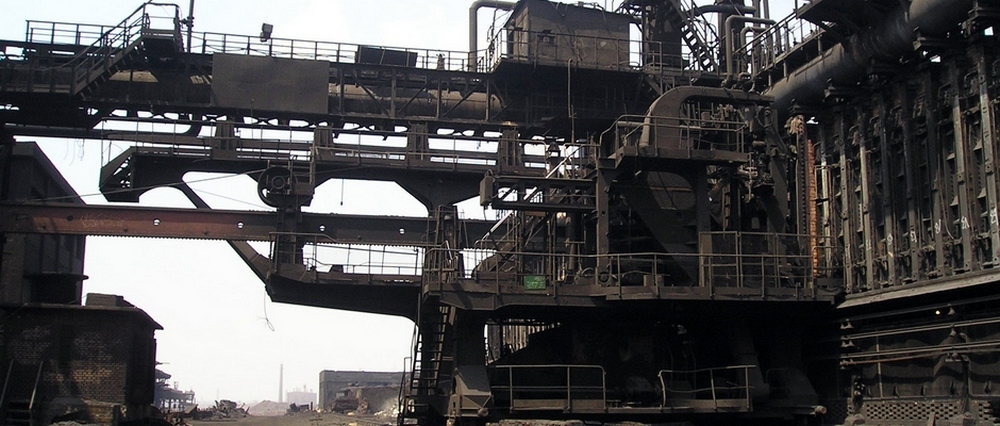

EQUIPMENT OF COKE OVEN BATTERY
Equipment to be embedded in the brickwork
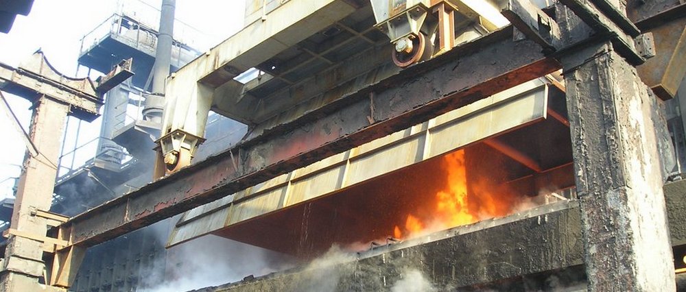
Conveyor for removal of coke spillage
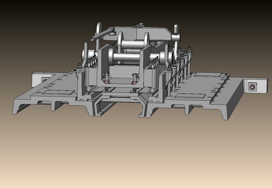
Lowering, swivel and stationary racks
Frames, flash plates, doors
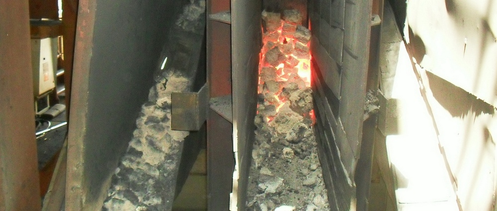
Coke oven flash plates
Flash plate is the basis for frame unit and it is designed for armoring of brickwork and protection of external part of chamber against mechanical damages.
Flash plate is manufactured in the form of U-shaped casting, covering the head of heating wall. Flash plates of adjacent walls are not linked up. On the bottom part of flash plate (from the side of chamber) the removable cast iron slab is fixed, it is the sole.
Technical features of flash plates
| Description of value | Oven volume, m3 | ||||||||
| 21,6 | 30,3 | 30,9 | 32,3 | 35,2 | 41,3- 41,6 | 51 | |||
| Height of oven, m | 4,3 | 5,0 | 5,0 | 6,0 | 5,5 | 6,0 | 5,5 | 7,0 | 7,0 |
| Length, mm | 5047 | 5680 | 6225 | 6712 | 6225 | 6712 | 6105 | 7735 | 7628 |
| Width, mm | 1138 | 1194 | 1254 | 1314 | 1254 | 1314 | 1294 | 1394 | 1564 |
| Height, mm | 474 | 430 | 430 | 430 | 430 | 430 | 430 | 430 | 450 |
| Weight, kg | 2057 | 2084 | 2457 | 2565 | 2457 | 2565 | 2570 | 3315 | 3861 |
Coke oven frame
Frame is the basis of coke oven door and it is designed for connection of two flash plates. It is the casting of difficult configuration, framing the chamber opening all over perimeter. It is fixed to flash plates by means of T-bolts.
Coke oven frame consists of frame, hooks, door latches are rested against them at closing of chambers, shoes, which door rollers are supported on, brackets, thrust screws, supported on flash plate through the support barrels.
Before machining, iron castings of frames, flash plates and door bodies are annealed.
Technical features of frames
| Description of value | Oven volume, m3 | ||||||||
| 21,6 | 30,3 | 30,9 | 32,3 | 35,2 | 41,3- 41,6 | 51 | |||
| Height of oven, m | 4,3 | 5,0 | 5,5 | 6,0 | 5,5 | 6,0 | 5,5 | 7,0 | 7,0 |
| Length, mm | 4972 | 5686 | 6166 | 6683 | 6166 | 6683 | 6146 | 7785 | 7795 |
| Width, mm | 830 | 854 | 970 | 870 | 970 | 870 | 1010 | 980 | 1060 |
| Height, mm | 430 | 475 | 470 | 495 | 470 | 495 | 610 | 602 | 610 |
| Weight, kg | 1160 | 1291 | 1407 | 1511 | 1407 | 1511 | 1620 | 2031 | 2163 |
Coke oven doors
Doors are designed for sealing of oven chambers from coke and pusher sides of battery. They are installed in gap, created with two adjacent flash plates and frame, mounted on them; they are fixed with latch gates.
There are three main executions of sealing frames manufactured of:
- ¢ sheet from stainless steel of thickness 1,5-2mm (diaphragm) and angle bar, framing the diaphragm over perimeter;
- ¢ non-equilateral machined angle bar with the strip, to be welded over perimeter;
- ¢ special profile (ą╩Ž-77,5-├╩ ęė 108.02.063-82).
The side adjoining to oven frame, is sharpened ¢ it is named knife and it is tightly pressed to frame mirror with effort to be created by means of latch gate.
Depending on design of stop device, doors are manufactured as follows:
- ¢ with screw gates;
- ¢ with spring gates.
Depending on dimensions and design, doors are equipped with two or three latch gates.

Flash plate, frame, door in assembly. Working electronic model.
Section through flash plate, door frame. Working electronic model.
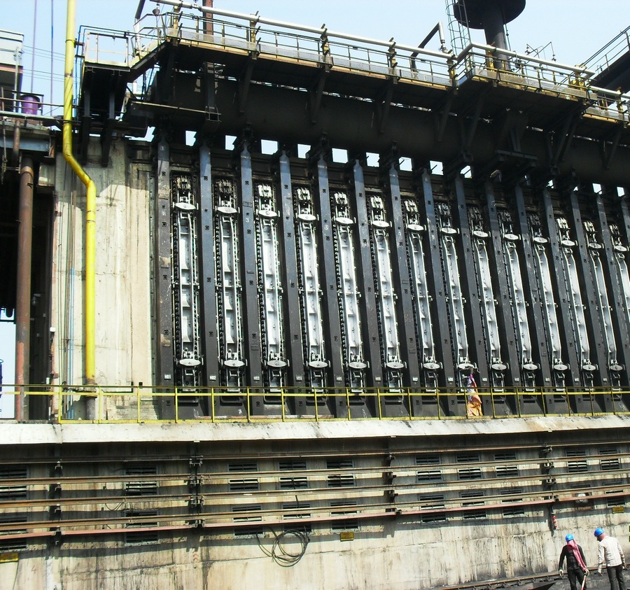
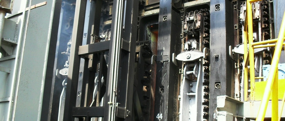
Frames, flash plates, doors of PJSC ōKB Koksokhimmashö design. Pusher side, COB No 11, IISCO, Burnpur, India
Equipment to be embedded in the brickwork
Charging hatch
Charging hatch is designed for closing and sealing of coke oven charging hole.
Hatch cover (variant 1) has centering pin and sector for gripping by hatch lifting device of coal charging car. Sealing of hatch cover with frame is knife type, ōmetal to metalö. Frame of hatch can be round or square section, made of heat-resistant cast iron; cover ¢ of steel casting.
Design of hatch (variant 2) is intended for lifting of cover using electromagnet hatch lifter.

Charging hatch in assembly (variant 1). Working electronic model.

Sectional view through charging hatch in assembly (variant 1). Working electronic model.

Charging hatch in assembly (variant 2). Working electronic model.
Top inspection eye
Top inspection eye is designed to control the vertical channels condition, replacement of burners and measuring of temperature in the channels. It is installed in the brickwork lining of the oven top.
Hatch consists of iron square body with the round through opening and lid with the bridge for the gripping of the lid while manual opening of hatch.

Section through top inspection eye in assembly. Working electronic model.
Eye to regenerator
Inspection eye is installed in insulation shields of regenerator mirrors. It is designed for surveillance of regenerator top, control of temperature and pressure in this area.
Diameter of inspection hole Dc, in mm: 40; 45.
Eye to regenerator. Working electronic model.
Insert with collar
Insert with collar shall be put into gun-flue laying to connect gun flue with heating pipes.
Insert shall serve as a fitting in gun flue laying and is used in heating systems with side gas delivery.

Insert with collar. Working electronic model.
Gas supplying equipment
Oven heating accessories
Coke oven gas heating accessories is designed for supply of coke gas from distribution gas main into heating system of coke ovens, and for supply of air for graphite removal of gas supply channels in ovens brickwork.
Depending on method of gas supply, it is manufactured of two executions:
- ¢ with bottom supply of coke gas;
- ¢ with lateral supply of coke gas.

Coke oven gas heating accessories with bottom supply of coke gas.

Coke oven gas heating accessories with lateral supply of coke gas. Working electronic model.

Air valve. Working electronic model.

Stop cock. Working electronic model.

Reversing cock. Working electronic model.
Blast-furnace gas heating accessories of coke ovens
Accessories is designed for supply and regulation of the blast-furnace gas and air quantity, supplied to the heating system of the coke ovens.
Periodic supply of the blast-furnace gas or air into the wall is performed by means of reversing cock Dn-150 of Dn-200.
Control of the cock is automatic by means of reversing winch and reversing mechanism. Gas supply switching off to the heating wall of the coke oven while repairing or replacement of the accessory details is provided by means of stop cock Dn -150 or Dn-200.

Blast-furnace gas heating accessories of coke ovens

Reversing cock Dn-200

Stop cock Dn-200
Reversing valves
To be applied in coke oven heating system and it provides as follows:
- ¢ at operation on blast furnace gas ¢ supply of blast furnace gas and air to regenerators and withdrawal of combustion products in flues;
- ¢ at operation on coke gas ¢ supply of air in regenerators and withdrawal of combustion products to flues;
- ¢ change of direction of gas air flows at reversing.
Reversing valves are divided into four assemblies:
| Assembly | Coe has heating | Blast furnace gas heating | ||
| before reversing | after reversing | before reversing | after reversing | |
| 1 | air supply into regenerator | air supply into regenerator | gas supply into regenerator | withdrawal of combustion products |
| 2 | air supply into regenerator | withdrawal of combustion products | air supply into regenerator | withdrawal of combustion products |
| 3 | withdrawal of combustion products | air supply into regenerator | withdrawal of combustion products | air supply into regenerator |
| 4 | withdrawal of combustion products | air supply into regenerator | withdrawal of combustion products | gas supply into regenerator |
Reversing valve of assembly 3 is designed for supply of air to regenerator at heating of battery ovens as blast furnace so coke gas and also for withdrawal of combustion products from regenerators to flues.
Reversing valve of assembly 3. Working electronic model.

Reversing valve of assembly 3 in section. Working electronic model.
On coke oven batteries with chambers having capacity 30m3 and more, double reversing valves are used, each of them service two adjacent bottom flues of regenerator.
In general, double valve is a block of two single valves, connected in one body, controlled with general lever system. Sometimes, withdrawal of combustion products is combined.
Double valve obtains widespread occurrence. In this valve the lids and disk valve are used for air supply and withdrawal of combustion products. Lids and disk valves are mounted in common body, and eversing and stop valves are used for supply of blast-furnace gas.
Combustion products from both adjacent bottom flues are withdrawn into flue through body and smoke branch-pipe.
In reversing valve of assembly 1-2 blast furnace gas is supplied into the left part of body and in assembly 2-1 reversing and stop cocks are installed in the right part.
Reversing valve of assembly 3-4 differs from valve of assembly 4-3 with the place of installation of reversing and stop cocks and both of them differ from reversing valves of assemblies 1-2 and 2-1 with the design of lever mechanism.

Reversing valve of assembly 1 ¢ 2. Working electronic model.

Reversing valve of assembly 1. Working electronic model.

Reversing valve of combustion products. Working electronic model.
Reversing devices
Reversing winch
Reversing winch is designed for switching of reversing valves and cocks. Reversing winch is installed in reversing premise.
Profile of winch washers provides required sequence of operating stroke and pauses at reversing of reversing cocks and valves. At swivel of gear-box shaft to 180░ the movement of levers to 610 mm is performed, it corresponds complete reversing.

Reversing winch. Working electronic model.
Winch of decarbonization device
Winch of decarbonization device is designed for opening and closing of covers of air valves through which air is periodically supplied in air channels of coke ovens for burning of graphite.
Crankshaft is carried out opening and closing of valve covers for passing of air in gas channels of coke ovens through lever system and control rod of reversing mechanism and levers of air valves. Manual drive is provided for closing of air valve covers during irregularity in electricity supply.
Winch of decarbonization device is installed in reversing premise of coke oven battery. Control of winch is automatically.
Hydraulic reversing device
Hydraulic reversing device is a drive for reversing mechanism. It is installed below the top foundation plate of coke oven battery.
Device is consisted from two drives and executes the following operations:
- - switching of reversing cocks of heating gas to change direction of supply of heating gas to heating walls;
- - switching of reversing valves for changing air supply to bottom flues of regenerators and withdrawal of combustion products from bottom flues to flues.
Hydraulic system is designed for actuating of hydraulic cylinders and consist of hydraulic drive station, control board, hydraulic distributors, stop accessories and pipe lines. Electrical provides control of reversing device.
Device may be equipped with three drives. Designation of the third drive Is opening and clothing of valves of air supply for decarbonization.
Devices is also available, in which compensation of drawing and tensioning of ropes performing by hydraulic cylinders of tensioning before each reversing.
Control of device is automatically. Devices are equipped with reserve manual pump and pneumo-hydraulic accumulator for operation in emergency situation.
| Drive for reversing cocks - effort into branch, kN - value of displacement, mm |
25; 35; 610 |
| Drive for reversing valves - effort into branch, kN - value of displacement, mm |
50; 70; 610 |
| Drive for valves of decarbonization: - effort into branch, kN - value of displacement, mm |
15 610 |

Hydraulic reversing device, COB No.11, IISCo, Burnpur, India.

Mnemonic diagram of reversing device, COB No. 11,Burnpur, India.
Reversing mechanism
Reversing mechanism is designed for periodically changing of direction of gas, air and combustion products flows. Mechanism is located in tunnel premise of coke oven battery.
Mechanism is actuated by reversing winch (or hydraulic reversing device) and decarbonization winch.
Scheme of connection of levers and valves to beams of reversing mechanism and also quantity of branches of reversing mechanism depends on scheme of coke oven heating, design of equipment and type of drive.
In ovens with bottom supply of coke oven gas, the air for decarbonization is supplied through reversive cocks at re-reversing, that is why the availability of decarbonization winch is not required.
Design, parameters and dimensions of mechanism depends on structural part of coke oven battery and type of reversing device.
| Efforts into links of reversing mechanism, kN in beams of reversing cocks in beams of reversing valves in beams of decarbonization valves |
15ģ35 30ģ70 8ģ15 |
Reversing mechanism with hydraulic reversing device. Working electronic model.
Gas withdrawal equipment
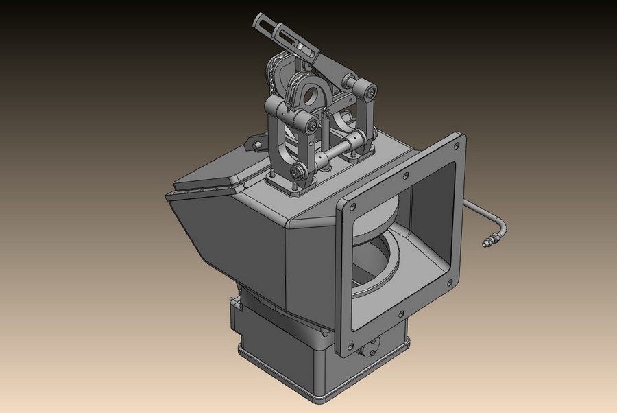
Gas withdrawal stand pipe
Gas withdrawal stand pipe is designed for connecting of coking chamber to gas collecting main at blend coking and its disconnecting at charging of chamber with blend. At connecting of chamber to gas collecting main, the closing of lid and actuating of stand pipe valve are executed and at disconnecting: opening of lid and closing of valve. Control of opening/ closing of lid and valve can be executed using hydraulic cylinder (hydroficated stand pipe) or mechanically (with mechanisms installed on coal charging car or manually).
Movable joint between elbow and valve box is executed on ōcoldö side and it is sealed with heat-resisting cord or hydraulic sealing.
Technical features of stand pipes
| Description | Nominal bore, mm | ||
| 390 | 500 | 550 | |
| Volume of oven to be serviced, m3 | 30ģ35,4 | 35,3 | 41,3 ¢ 41,6 |
| Type of drive | hydraulic lever |
hydraulic lever |
hydraulic lever |
| Length, mm | 1900 | 2370 | 2035 |
| Width, mm | 910 | 1234 | 1105 |
| Height, mm | 1580 | 1645 | 4020 |
| Weight, kg | 1440 | 1830 | 2582 |

Gas withdrawal stand pipe with hydraulic sealing of lid. Working electronic model.

Gas withdrawal stand pipes with hydraulic sealing of lid and lever control, COB No 11, IISCO, Burnpur, India.
Shorten stand pipe
Shorten stand pipe (fig. 1) is designed for evacuation of gas to be created at oven charging, through adjacent chamber into gas collecting main. At this scheme the overlapping device is used, it connects shorten stand pipes and adjacent oven to be ready to pushing. Sealing of lid of stand pipe can be hydraulic or pneumatic.
Control of stand pie lid is executed from coal charging car.
Technical features of stand pipes
| Description of value | Nominal bore, mm | ||
| 510 | 610 | ||
| Volume of oven to be serviced, m3 | 30 | 35,3 | |
| Type of drive for lifting of lid | electro-magnetic | electro-magnetic | |
| Length, mm | 820 | 870 | |
| Width, mm | 1080 | 870 | |
| Height, mm | 930 | 914 | |
| Weight, kg | 317 | 395 | |
Shorten stand pipes, Avdeyevskiy coking plant, Ukraine.
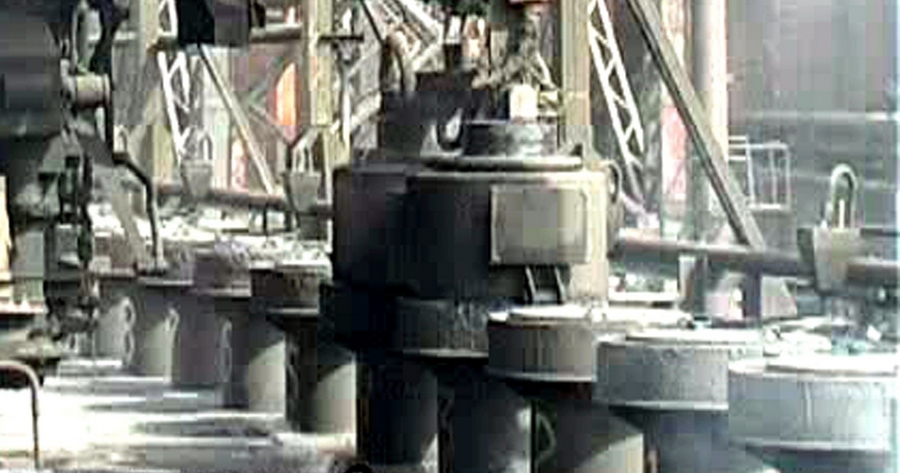
Gas collecting main
Gas collecting main is designed for sampling, primary cooling and withdrawal of coke gas.
It is installed on the top of coke ovens and it is connected with coking chambers through stand pipes.
Gas collecting main is manufactured for pusher and coke sides of battery. Generally, gas collecting mains differs with availability of hydraulic gate and direction of slopes for coal-tar products descending (to hydraulic gate or to t-joint). The shape of cross-section of gas collecting mains can be round or U-shape type.
Depending on quantity of gas to be supplied from coke ovens, gas collecting main are made with one or two cross over gas mains.

U-shape gas collecting main, gas bleeder, cross over main, COB No 11, IISCO, Burnpur, India
Cross over gas main
Cross over gas main is designed for joint of gas collecting mains and withdrawal of coke gas from them to gas main.
It is joined to t-joints of gas collecting mains and flange of plant gas main.
At installation of gas collecting main on battery from pusher side, functions of gas main are executed by the pipe unit to be joined to direct coke gas pipeline.
Cross over gas main is equipped with compensator, spray nozzles and throttle valves for regulation of pressure in gas collecting mains.
Technical features
| Oven volume, m3 | 21,6- 30 | 30,3- 35,3 | 41,3 ¢ 51 |
| Diameter f nominal bore, mm | 1200-1400 | 1400 | 1400 |
| Weight, kg | 20200 | 23500 | 26200 |
Cross over gas main. Working electronic model.
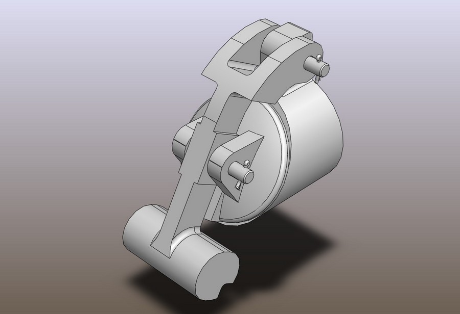
Steam/hydro injection cocks
Steam injection cock is designed for supply of steam and hydro injection cock is for water supply to the elbow of stand pipe at charging of coke oven.
Cocks are produced in two executions: with right and left location of handle.
Cocks control can be manual and by means of mechanism to be installed on coal charging car.
Technical features
| Nominal bore, mm | 25 |
| Pressure of steam, kPa/ water, MPa | 880/4 |
| Steam temperature, °č | 400 |
| Weight, kg | 7,3/12 |

Hydro injection cock. Working electronic model.
Nozzles and sprayers
Nozzle is designed to cool coke gas by means of water spraying. Water is supplied to nozzle under low for irrigation and under high pressure for hydro-injection. Nozzles are installed on stand pipe elbow.
Presence of two chambers ensures formation of required flame jet structure for hydro-injection and cooling.
Sprayer is designed for cooling of coke gas by means of water sprinkling which supplied under pressure. Sprayers are installed on gas collecting main and cross-over gas main.

Irrigation sprayer. Working electronic model.
Irrigation sprayer. Working electronic model.

Irrigation nozzle. Working electronic model.

Irrigation nozzle. Working electronic model.
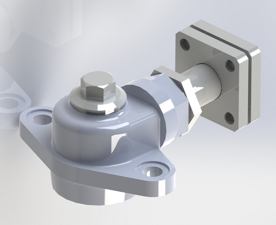
Manual slide gate
Manual slide gate is designed for adjustment of draught in flue of coke oven battery.
Rotation angle of slide gates, degree ģ 0 ¢ 85░č

Manual slide gate. Working electronic model.

Slide gate with manual drive. Working electronic model.
Automatic slide gate
Automatic slide gate is designed for automatic adjustment of draft in chimney flues.
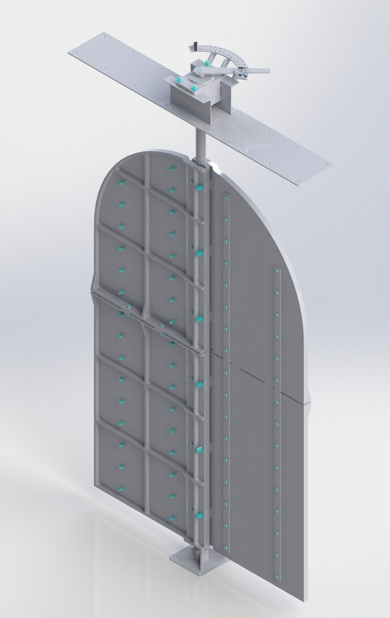
Automatic slide gate. Working electronic model.
Coal tower gates
Coal tower gates are designed for opening and closing of discharge holes of coal tower hoppers.
There are three or four gates in one row. Typical coal tower has from six up to nine rows. As per design the gates can be of the I-st or the II-nd type.
Technical features
| Execution | I | II |
| Stroke of lever, mm | 314 | 314 |
| Effort on lever, N | 980 | 980 |
| Area of outlet hole of gate, m3 | 0,25 | 0,27 |
| Width of gate, mm | 500 | 600 |
| Weight of one row (3 gates), kg | 2185 | 1720 |

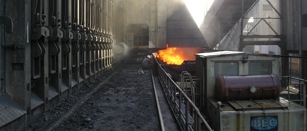
Coal tower gates, COB No 11, IISCO, Burnpur, India.
Skip hoister
Skip hoister is designed for transportation of leveling coal blend from bottom hopper to the top one, from which the coal blend is discharged cyclically to the hopper of coal charging car.
Skip hoister is installed on the pusher side of battery at the coal tower. Skip hoister can service two batteries if the coke oven plant arrangement is standard. Operation of the hoister is automated, and sensor system shows when and what technological operations are to be executed. Lubrication of bearing units of the hoister is consistent, manual.
Skip hoister is supplied as per the specification of general arrangement drawing of item set along with electric equipment.
Spare parts are supplied as per agreement with Purchaser.

Skip hoister. Working electronic model.
Conveyor for removal of coke spillage
Conveyor is designed for removal of coke spillages formed at door extraction from coke oven.
Installation of conveyor is executed from pusher and coke sides of battery in the cavity of servicing platform. Drive of conveyor and tensioning device provide reliable operation of scraper chain, which moves in the trough and executes the transfer of spilled coke in collecting bunker.
Technical features
| Volume of oven to be serviced, m3 | 21,6 ¢ 41,6 |
| Distance between axes of the end ovens, mm | 70560-92300 |
| Production output, t/hour | 2,5 |
| Length over axes of drive and tensioning device, L, mm | 108980-159980 |
| Width, B, mm | 2715 |
| Height, H, mm | 2970 |
| Weight, kg | 12506-16680 |

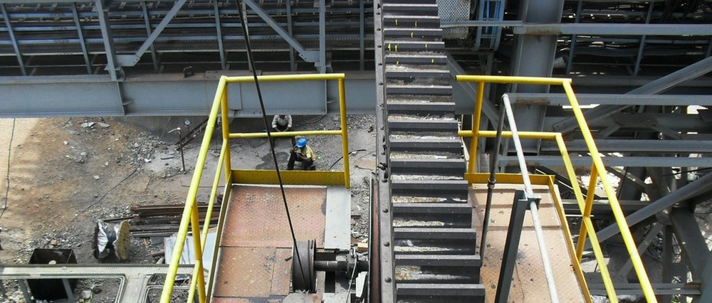
Conveyor, COB No11, IISCO, Burnpur, India.
Lowering, swivel and stationary racks
Equipment is designed for current repair and storage of coke oven doors with volumes of chambers 21,6¢41,6 m3 and height 4300 ¢ 7000 mm
Equipment is installed at the end platform of coke oven battery from pusher and coke side.
| Equipment | Parameters | Oven height, m | ||||
| 4,3 | 5,0 | 5,5 | 6,0 | 7,0 | ||
Stationary rack |
Length, mm | 1216 | 1298 | 1298 | 1228 | 1300 |
| Width, mm | 750 | 980 | 950 | 910 | 1035 | |
| Height, mm | 5500 | 6630 | 6630 | 7130 | 8000 | |
| Weight, kg | 881 | 620 | 635 | 687 | 673 | |
Swivel rack |
Length, mm | 2330 | 2000 | 2200 | 2330 | 2330 |
| Width, mm | 2330 | 2000 | 2200 | 2330 | 2330 | |
| Height, mm | 5560 | 7080 | 6590 | 7080 | 8140 | |
| Weight, kg | 1491 | 1955 | 1840 | 1595 | 1675 | |
| Unit of lowering racks (electro-mechanical drive; 2 racks) | Length, mm | 14730 | 16200 | 11500 | 15140 | 17100 |
| Width, mm | 5120 | 14000 | 16500 | 11350 | 16500 | |
| Height, mm | 5350 | 6990 | 6983 | 7540 | 8233 | |
| Weight, kg | 5596 | 14876 | 13180 | 12010 | 15600 | |
| Unit of lowering racks (hydro-mechanical drive; 2 racks) | Length, mm | 2280 | 2310 | |||
| Width, mm | 2000 | 6983 | ||||
| Height, mm | 6983 | 8433 | ||||
| Weight, kg | 13180 | 15500 | ||||

Lowering rack. Working electronic model.

Stationary rack, COB No 11, IISCO, Burnpur, India.
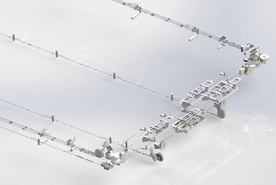
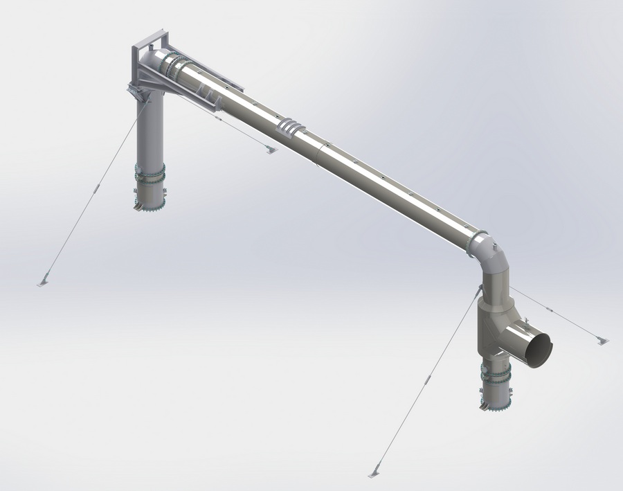
Duct of PEC
Duct is a component part of land-based pushing emission control unit (PEC) and it is designed to receipt and withdraw of dust-gas mixture, emitted while coke pushing from coke ovens.
Duct is installed from the coke side of the battery on the supports. One of supports is fixed, the rest are movable, roller supports.
On the top surface of duct, the railway track is mounted, belt-lifting car of coke guide car moves on it.
In the top part of duct, the gap is available, it is closed with belt, and the tensioning of belt is executed by means of tensioning device of cargo type.
Tensioning of belt can be regulated by changing the number of counter-weights. Placement of belt align center is provided with side rests, installed on duct
Operation of pushing emission control duct as suction pipeline is provided with operation of fan unit. In the period of coke discharging, it creates negative pressure in duct at the distant oven ¢ 800-1000 Pa. In the period between coke discharging ¢ not more than 500 Pa.
Duct is equipped with small hatches for servicing and repair of duct.
Technical features
| Oven volume, m3 | 21,6 | 30,9 | 35,3 | 41,6 |
| Number of ovens in battery | 65 | 65 | 77 | 37§2 |
| Cross over section area, m2 | 2,12 | 2,36 | 2,46 | 2,67 |
| Length, mm | 259680 | 263720 | 173545 | 242150 |
| Width, mm | 2195 | 2015 | 2115 | 1860 |
| Height, mm | 4070 | 3950 | 4470 | 2387 |
| Weight, kg | 200000 | 188300 | 133216 | 195000 |

Duct of PEC. Working electronic model.

Duct of PEC. Working electronic model.

Duct of PEC.